|
|
|
|
|
|
|
|
|
|
|
|
|
|
|
|
|
|
Air of Authority - A History of RAF Organisation
|
|
|
|
|
|
|
|
|
|
|
|
|
|
|
|
|
|
Development of Squadron Markings and Codes 1939 - 1945
By 1944 most of the developments in camouflage, colouring and markings had been incorporated into Air Publication 2656A. The details given below amended up to and including Amendment List No 8 (AL8) of October 1944.
Chapter 2 IDENTIFICATION mARKINGS
Introduction
1. Identification markings on aircraft are of the following types:--
(i) National marking - roundel
(ii) Code letters.
(iii) Serial number.
(iv) Tail fin marking
(v) Additional markings for aircraft with special roles.
National marking-roundel
2. The four types of. roundel in use are shown in fig. 1 to 4. The roundel to be used on any particular type of aircraft can be found from Table I at the end of this Chapter.
Colour added by the author
3. DIMENSIONS OF NATIONAL MARKING - ROUNDEL
(i) National marking I.- If the distance between the control surfaces on the wing exceeds 7 ft. 2 in. the diameter of the outer ring is to be 7 ft. with equal margins fore and aft. The diameter of the outer ring shall in no case be less than 2 ft. 6 in. The diameter of the red disc is two-fifths that of the blue ring.
(ii) National marking II, III and IV.- The diameter varies with the type of aircraft, as follows:-
| Type of aircraft | Outside diameter of each colour band in inches | |||
| Red | White | Blue | Yellow (National Marking III only) | |
| Small | 6 | 8 | 16 | 18 |
| Medium | 12 | 16 | 32 | 36 |
| Large | 18 | 24 | 48 | 54 |
Note ....For single seat fighters the roundels to be used are those shown for medium size aircraft. The large sizes are to be used on heavy bombers and the small on light trainer types or other aircraft which have slim or boom type fuselages where it is impracticable to apply a larger size of roundel.
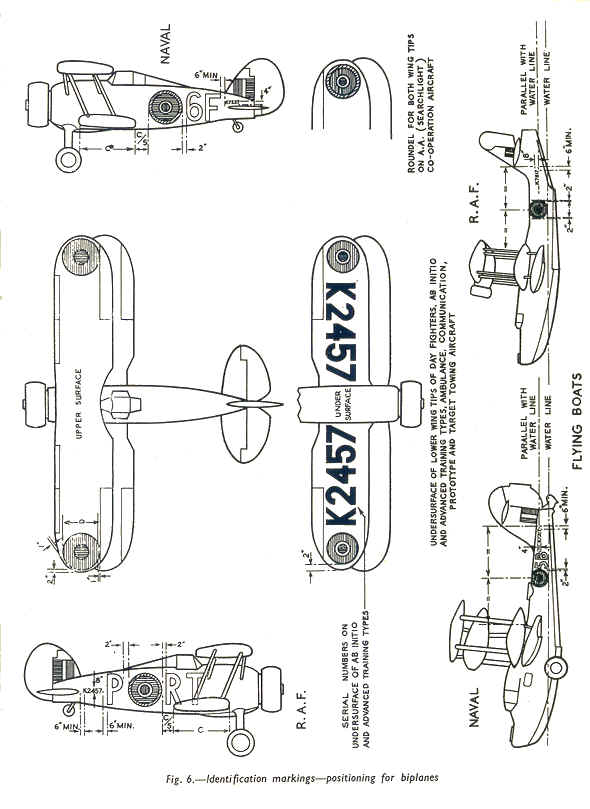
4. Location of national marking - Roundel - The positions of the roundels are shown in 5 and 6.
fig 5.
 fig 6.
Code letters
Colours
5. The code letters, known as identification marking 'A', consist of the squadron two-letter code and the aircraft letter. These are located on each side of the fuselage adjacent to the roundel and are applied in the following colours: -
(i) SKY - For day fighters and Fighter Command O.T.U. aircraft, excluding night fighters
(ii) LIGHT SLATE GREY.-For Coastal Command aircraft which have white under-surfaces .
(iii) DULL RED.-For other operational aircraft and O.T.U. aircraft, excluding Fighter Command O.T.U. day fighter aircraft.
6. The spacing and dimensions for standard code letters are given in fig. 7. Smaller letters only when the space available is insufficient for the standard sizes. Between letters and the roundel there should be a 2 in. space.
Positioning
7. The squadron two-letter code may be applied either forward or aft of the fuselage roundel according to the space available. The single aircraft letter is then to be applied at the opposite side of the rouiidel. The two letters of the squadron code are not to be
separated under any circumstances; for example:-
Squadron code letters TP
Aircraft letter R
Port side R roundel TP, reading from left to right
Starboard side TP roundel R, reading from left to right.
8. On aircraft where the mainplane is set farther aft than normally (for example, aircraft with tricycle undercarriages), the squadron code letters may be applied either forward or aft of the fuselage roundel, and the aircraft letter immediately forward of the leading edge of the mainplane. In such instances, however, the squadron letters must be positioned in same manner relative to the roundel (forward or aft) on both sides of the aircraft.
Dimensions
6. The spacing and dimensions for standard code letters are given in fig. 7. Smaller letters only when the space available is insufficient for the standard sizes. Between letters and the roundel there should be a 2 in. space.
Serial number
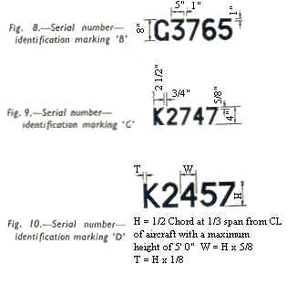
9. The serial number of an aircraft normally appears on the sides of the fuselage and on the under surfaces of the wings (the lower wings of
a biplane). It is initially applied by the aircraft manufacturer and should be faithfully copied when an aircraft is being re-finished. Three types of serial numbers, as shown in fig. 8, 9, and 10 are in use. The type of serial number, and the colour of the number, to be used on any particular type of aircraft can be obtained from Table 1 at she end of this chapter.
10. LOCATION OF SERIAL-NUMBERS. - See Table 1 and fig. 5 and 6.
Tail fin markings
11. A standard tail fin marking is shown in fig. 11, the width and height of stripes being as stated in para. 12. The marking should appear on both sides of the fin and on both sides of each fin of an aircraft with twin rudders. Variations of the standard marking are permitted for differing types of fin as follows: -
(i) STANDARD MARKING - The standard marking shown in fig. 11 is to be used wherever possible. The base of the marking is to be either the top of tail plane or the continuation of the top fuselage line, whichever gives the better vertical surface. The rear edge of the marking is to coincide with the the rear edge of the fin where the arrangement shown in fig. 11 is not possible, the centre line of the fin should coincide with the centre line of the white stripe, the red and blue stripes being of equal width
(ii) Where the leading edge of the fin makes an angle with the base of the fin of 60o or more, the centre line of the fin should coincide with the centre line of the white stripe, the red and blue stripes being of equal width. (see fig. 12).
(iii) Where the leading edge of the fin makes an angle of less than 60o with the base of the fin, the forward edge of the vertical red stripe should commence 6 in. to the rear of the most forward point of the fin base (see fig. 13).
(iv) Where the rudder overhangs the fin to an extent less than two-thirds of the overall height of the fin, a vertical line should be dropped to the tailplane from the angle of the cut-away portion of the fin. This line limits the rear edge of the blue stripe (see fig. 4).
(v) Where the fin extends below the tail plane (on the Cygnet, for example) the lower limit of the stripes is determined by the upper surface of the tailplane (see fig. 15).
(vi) In exceptional instances where the fin overhangs the rudder, the line of the rear edge of the fin at the hinge should be produced upwards to limit the rearward edge the blue stripe (see fig. 16).
(vii) Where the rudder overhangs the fin to an extent more than two-thirds of the over-all height of the fin, the height of the stripes should be determined by a horizontal line produced forward from the angle of the cut-away portion of the fin. (see fig. 17).
Figures 11 - 17 -
 Images redrawn by author
12. DIMENSIONS OF FIN MARKINGS.- The dimensions vary with the type of aircraft, as follows:-
| Type of aircraft | Width of flash (in.) | Height of flash (in) | Width of colour band (in) | ||
| Red | White | Blue | |||
| Small | 18 | 24 | 8 | 2 | 8 |
| Medium | 24 | 24 | 11 | 2 | 11 |
| Large | 36 | 24 | 17 | 2 | 17 |
Additional marking for aircraft with special roles
13. PRESENTATION AIRCRAFT.-To distinguish presentation or other particular aircraft, a marking not larger than 9 in. by 6 in., or an inscription in 2 in. letters may be applied to the sides of the fuselage forward of the leading edge of the wing, subject to authority being given through Headquarters of the Command concerned. This marking should be in medium sea grey.
14. PROTOTYPE AIRCRAFT.-Aircraft finished with prototype camouflage should carry the standard marking for Service aircraft, and in addition, the letter 'P' encircled by a ring on each side of the fuselage adjacent to the roundel. The line forming the ring should be 1/2 in. in width, and the outside diameter of the ring should be equal to that of the roundel. The lines forming the letter 'P' should be 3 in. in width, and the extremities of the letter should in. from the inside of the ring. The colour of both ring and letter should be yellow.
Finishing materials
15. Finishing materials for the identification marking of aircraft are manufactured to the same specifications as camouflage finishes and may be of cellulose or synthetic composition. When painting identification markings it is important to use colours of the same type (C or S) as the camouflage finish of the aircraft. The camouflage finish can be identified by the method described in Sect. 1, Chap. 2.
Boundary between colours
16. When applying identification colours a precise dividing line is necessary between the identification colours and the adjacent finish. At the same time the colours should be applied evenly and not too thickly, so as to preserve the overall smoothness of the aircraft.
The colours mentioned in the text can be
seen by clicking on this thumbnail: - 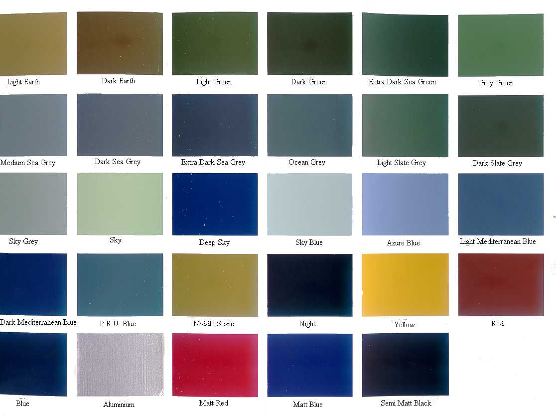
This page was last updated on 17/03/25©
![]() Chapter 1
Table
1 - AP 2656A
Chapter 1
Table
1 - AP 2656A
![]()